- Explain Captain/Dispatcher joint responsibility.
The captain and dispatcher are jointly responsible for the preflight planning of each flight. They shall determine the suitability of weather, field, traffic, airway facilities. Both have the authority to delay flight. Any time the flight cannot be conducted in accordance with the release, the first person encountering such information shall contact the other to institute the necessary amendment to the release.
Vol 1, 20.20 Pg. 2
- When is an alternate required?
Mnemonic = 1-2-3 / 1500&2 / 2000&3 / MMOISRS / 3585
- 1-2-3 = The basic 1-2-3 rule: 1 hour before to 1 hour after ETA, ceilings 2,000 or more, vis 3 SM or more.
- 1500&2/2000&3 = For flag operations, ceiling 2,000 AFE, or 1,500 above lowest approach mins, (whichever is greater), and vis 3 SM or 2 SM above lowest approach mins (whichever is greater).
- M = Marginal: within 100 OR ½ of Cat 1 mins at destination, AND within 100 OR ½ of DERIVED mins at 1st alternate. 2nd alternate required.
- M = Method 2. Engine failure at cruise, clear all obstacles by 2,000 feet, 5 SM either side of route — but if failure occurs before reaching cruising alt, we need to be able to return to departure airport, or divert to a takeoff alternate using Method 1 calculations
- O = Offline charters
- I = International (when only 1 runway or flight time >6 hours — and NO 3585!)
- S = Severe icing
- R = RNAV only approach (alternate must have non-RNAV approach)
- S = Supplemental
- 3585 = 3585: destination = not less than ½ the vis for the expected approach. 1st alternate not less than ½ ceiling and vis of DERIVED alternate mins. 2nd alternate at or above DERIVED alternate mins.
- How do we compute landing distance? Normal procedures. Alternate procedure.
- Normal procedure = AOC landing performance assessment.
- Alternate procedure = QRH Landing Performance Table
- If using alternate procedure, also the Max landing weight tables to ensure missed approach climb performance.
Vol 2, 3.15 pg. 9
- Explain Method 1 vs Method 2. Standard strategy vs Obstacle. Procedures for both. Where would we see it listed?
METHOD 1 VS METHOD 2
- Method 1 – enroute obstacle clearance required from V1 to the destination, clear all obstacles by 1000 feet / 5 sm.
- Method 2 (driftdown), engine failure at cruise altitude, the aircraft must be able to divert to at least one suitable airport, clearing all obstacles by 2,000 feet / 5 sm.
Vol 1, 20.32 Pg. 5-6
STANDARD STRATEGY VS OBSTACLE STRATEGY INITIAL PROCEDURE
- Standard Strategy:
- Set MCT, disconnect A/THR.
- Descend at .78/300 (or .77/270 in the NEOs).
- Obstacle Strategy:
- Set MCT, disconnect A/THR
- Remain level until slowing to Green Dot, then descend at Green Dot
- Revert to Standard Strategy when clear of all obstacles.
Vol 2, 8.01 pg. 8-9
WHERE WOULD WE SEE IT LISTED?
On Page 1 of the release, between the flight plan block and the MELs, there’s the Planned Takeoff / Max Planned Takeoff Weights. In that block is specified either Method 1 of Method 2. If Method 2, drift down points and diversionary airports are specified.
Vol 1, 20.32 Pg. 2
5a. Explain the following flight mode:
NORMAL
Bank protection, yaw damping & turn coordinating, pitch protection, high AoA protection, load protection, high speed protection.
Vol 3, 27.20.10
5b. Explain the following flight mode:
ALTERNATE
No bank protection, yaw damping, no pitch protection, low speed stability (stall warning vs high AoA protection), load factor protection, high speed stabilities.
5c. Explain the following flight mode:
DIRECT
No protections, mechanical ruddder, stall warning, no load protection, overspeed warning.
5d. Explain the following flight mode:
MECHANICAL BACKUP
Temporary mode in case of complete electrical failure. Remaining controls are rudder, horizontal stabilizer, and engine thrust.
5f.~~Explain the following flight mode:~~
~~High/low speed and high AOA protections~~
HIGH SPEED PROTECTION
The aircraft automatically recovers following a high speed upset. Depending on the flight conditions (high acceleration, low pitch attitude), the High Speed Protection is activated at/or above VMO/MMO.
When it is activated, the pitch trim is frozen (on A319 only), spiral static stability is introduced to 0° bank angle (instead of 33° in normal law), and the bank angle limit is reduced from 67° to 40°. The pitch trim is limited between the setting at the aircraft’s entry into this protection and 11° nose-up. As the speed increases above VMO/MMO, the side-stick nose-down authority is progressively reduced, and a permanent nose-up order is applied to aid recovery to normal flight conditions.
The High Speed Protection is deactivated when the aircraft speed decreases below VMO/MMO, where the usual normal control laws are recovered.
The flight crew should never deliberately fly the aircraft beyond VMO/MMO, unless absolutely necessary for operational reasons, such as avoiding another aircraft.
The pilot should, as soon as possible, reduce resistance to the High Speed Protection and allow the aircraft to return to a speed below VMO/MMO, by smoothly relaxing the forward stick force to attain a comfortable nose-up pitch rate. It is not usually necessary to apply a pull force to recover. If a quicker recovery is required for operational reasons, the pilot should pull back smoothly and progressively, monitoring the g indication on the ECAM.
LOW SPEED PROTECTION
An aural low energy warning, “SPEED SPEED SPEED” synthetic voice sounds every 5 seconds whenever the aircraft energy (as computed by the FAC) goes below a threshold under which thrust must be increased in order to recover a positive flight path angle.
During acceleration, the warning is triggered before alpha floor (unless alpha floor is triggered by stick deflection). The amount of time between the two warnings depends on deceleration rate.
The low energy warning is available in CONFIG 2, 3, and FULL.
The low energy warning is inhibited:
- When TOGA is selected; or
- Below 100 feet RA; or
- Above 2000 feet RA; or
- When alpha floor or the ground proximity warning system alert is triggered; or
- In Alternate or Direct Law; or
- If both radio altimeters fail.
If the Low Energy condition persists, Alpha Floor is triggered.
HIGH ANGLE OF ATTACK PROTECTION
The aircraft resists attempts by either a pilot or the atmosphere to stall it. If a pilot attempts a stall, he/she feels the aircraft trying to pitch down as speed approaches the amber and black strip. The pilot can resist this tendency until speed reaches the red band (αMAX), and then further nose-up control is not available. Between these two points, floor automatically sets go around thrust. The pilot can hold full back stick, if it is needed (see wind shear), and the aircraft stabilizes at an angle of attack close to but short of the 1g stall.
WHEN FLYING AT αMAX, THE PILOT CAN MAKE GENTLE TURNS, IF NECESSARY.
As the aircraft enters protection at the amber and black strip (αPROT), the system inhibits further nose-up trim beyond the point already reached. Nose-down trim remains available if the pilot pushes the stick forward.
5g.~~Explain the following flight mode:~~
~~ALPHA LOCK~~
ALPHA/SPEED LOCK FUNCTION (SLATS)
The alpha/speed lock function inhibits slat retraction at high angles of attack and low speeds. The Slat Flap Control Computers (SFCCs) use angle of attack (alpha) or airspeed information from the ADIRUs to inhibit slat retraction.
The alpha/speed lock function is activated when:
- Alpha exceeds 8.6° or
- Airspeed falls below 148 knots
Results of alpha/speed lock function: Retraction from position 1 to position 0 is inhibited.
Inhibition removed when:
- Alpha falls below 7.6° or
- Speed exceeds 154 knots
Alpha/speed lock function not active if:
- Alpha exceeds 8.6° or airspeed falls below 148 knots after pilot has moved the flap lever to 0; or
- Aircraft is on ground with speed less than 60 knots
- Explain Ground Speed Mini:
A FMGC computed approach speed based on VAPP, surface winds, and winds aloft. It maintains a constant ground speed instead of maintaining a constant indicated airspeed.
~~The purpose of the ground speed mini function is to take advantage of the aircraft inertia when the wind conditions vary during the approach. It does so by providing the crew with an adequate indicated speed target. When the aircraft flies this indicated speed target, the energy of the aircraft is maintained above a minimum level ensuring standard aerodynamic margins versus stall. If the A/THR is active in SPEED mode, it will automatically follow the IAS target, ensuring an efficient thrust management during the approach. The minimum energy level is the energy level the aircraft will have at touch down if it lands at VAPP speed with the tower reported wind, as inserted in the PERF APPR page. The minimum energy level is represented by the Ground Speed the aircraft will have at touchdown. This Ground Speed is called “GROUND SPD MINI”. During the approach, the FMGS continuously computes the speed target, using the wind experienced by the aircraft, in order to keep the ground speed at or above the “Ground Speed Mini”. The lowest speed target is limited to VAPP, and its upper limit is VFE of next configuration in CONF 1, 2 or 3 and VFE - 5 in CONF FULL. The speed target is displayed on the PFD speed scale in magenta, when approach phase and managed speed are active. It is independent of the AP/FD and/or ATHR engagements. Wind is a key factor in the ground speed mini function.~~
Vol 2, 10.47 pg. 1
7a. Preliminary Cockpit Prep
What is the minimum Bat voltage and what does that voltage ensure?
- 25.5 volts
- Ensures 50 % Bat charge
Vol 2, 3.05 pg. 3
7b. Preliminary Cockpit Prep
What indications do you get when performing the APU Fire test WITHOUT AC Power?
- APU Fire pushbutton illuminates (half of the lights)
- Squib and Discharge light both illuminate
Vol 2, 3.05 pg. 3
7c. Preliminary Cockpit Prep
Referencing 7b, what additional indications do you get when AC power is available?
- Master Warning flashers
- CRC
- ECAM
Vol 2, 3.05 pg. 3
- If Brake accumulator pressure is out of green band, how can it be charged?
Turn on the Yellow electric pump.
Vol 2, 3.05 pg. 4
- At the gate with the engines off, you turn on the yellow hydraulic pump. Will this action pressurize the green hydraulic system?
YES.
If you turn on the Yellow Electric Pump, this action will pressurize the Yellow System directly, and pressurize the Green system via the PTU.
However, PTU is inhibited when:
- One engine running and parking brake on.
- One engine running, parking brake off, and N/W DISC.
- 40 seconds after cargo door operation.
Vol 2, 3.05 pg. 4
Vol 3, pg. 1795
- How do you perform an alternate brake check?
NOTE: The purpose of this check is to verify the efficiency of the alternate braking system (absence of “spongy pedals”).
- (F/C) Y ELEC PUMP . . . CHECK OFF
- (F/C) CHOCKS . . . CHECK IN PLACE
- (F/C) PARKING BRAKE . . . OFF
- (F/C) BRAKE PEDALS . . . PRESS
Apply maximum pressure on both pedals.
- (F/C) BRAKE PRESSURE (on BRAKE press indicator) . . . CHECK
Pressure must build up without delay symmetrically on left and right sides for the same application simultaneously applied on left and right pedals. With full deflection of the left and right pedals, pressure must be between 2000 and 2700 psi.
- (F/C) BRAKE PEDALS . . . RELEASE
- (F/C) PARKING BRAKE . . . ON
The parking brake must be on during the exterior inspection to allow the flight crew to check brake wear indicators.
Vol 2, 3.05 pg. 4
- What is the minimum engine oil quantity for flight?
CEO 9.5 qt + 0.5 qt per hour of estimated flight time
NEO the highest of 10.6 qts or 9.0 qts + 0.5 qts per hr
Vol 2, 2.10 pg. 7
Vol 2, 3.05 pg. 5
- During single engine taxi, the #2 engine must be started a minimum of how many minutes prior to take off and why?
5 minutes.
- We need to let the engines warm up in order to prevent thermal shock. Warm-up time has been standardized to 3 minutes across the fleet. And, coincidentally, we also need to let the Center Tank Transfer cycle complete its 2 minute test on some of our older planes to make sure the engines are feeding off their respective, separate wing tanks.
- The NEOs can take up to 2 minutes to start, so 2 + 3 = 5.
Vol 2, 3.10 pg. 6
- What temp and conditions must the engine anti-ice be turned on and in what phase of flight?
First, definition of icing conditions:
- OAT (on ground) or TAT (in flight) at or below 10°C
- visible moisture (clouds, fog, rain, etc) or standing water, slush, ice or snow on taxiways or runways. (Vol 2, 5.45 pg. 9)
- ENGINE ANTI-ICE must be ON during all ground and flight operations, when icing conditions exist, or are anticipated, except during climb and cruise when the SAT is below -40°C.
- ENGINE ANTI-ICE must be ON during a descent in icing conditions, even if the SAT is below -40°C. (Vol 2, 5.45 pg. 10)
- WING ANTI-ICE WING ANTI-ICE may either be used to prevent ice formation, or to remove ice accumulation from the wing leading edges. WING ANTI-ICE should be selected ON whenever there is an indication that airframe icing exists. This can be evidenced by ice accumulation on the visual ice indicator (located between the two cockpit windshields) or on the windshield wipers. (Vol 2, 5.45 pg. 10)
- If icing conditions last longer than 30 minutes, or if vibration occurs, the engines must be run-up to 70% N1 for a sustained period of at least 30 seconds, if ground surface conditions and the environment permit. If ground surface and environment do not allow acceleration to 70% N1 then power setting and run-up time should be as high as practical. This run-up should be accomplished just prior to takeoff, with particular attention paid to the engine parameters to ensure normal operation. (Vol 2, 5.45 pg. 9)
- Weight and balance. What ways can you get a valid W&B?
- ACARS Weight Balance / Performance (AWP).
- Computerized Weight and Balance Manifest.
- Flight Crew Readback form
Vol 2, 3.10 pg. 1
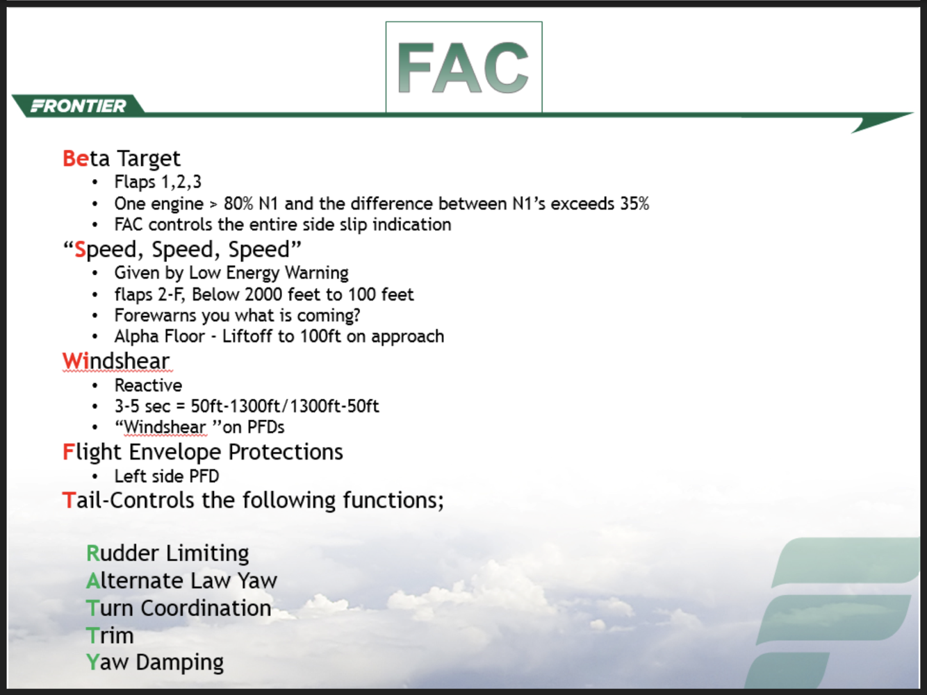
- What do the FACs do?
- Beta target
- Low Energy warning
- Reactive windshear
- Flight envelope protections (all the markings on the speed tape)
- Tail functions – yaw damping, turn coordinating, rudder travel limiter, rudder trim, alternate law yaw
- When is a TO Alternate required?
When departure airport is below CAT I mins.
Vol 1 20.40 Pg. 3
- What is the time and distance for a TO alternate?
- Max time of 1+00 (normal cruise speed, single engine, still air)
- max distance of 330 nm.
Vol 1, 20.40 Pg. 3


-
Memory Items8
-
Limitations81
-
Alternates14
-
Big 8992
-
Initial Upgrade Exam41
-
Cards That Need Updating5
-
Flight Control Laws27
-
Random15
-
ADIRS PANEL21
-
Flight Controls Panel18
-
EVAC Panel2
-
Emergency Panel12
-
GPWS Panel5
-
Recorder Panel5
-
Oxygen Panel7
-
Calls Panel4
-
Rain Panel2
-
External Lights Panel3
-
APU Panel5
-
Signs Panel3
-
Interior Lights Panel1
-
Anti Ice Panel10
-
Probes / Window Heat Panel2
-
Cabin Pressurization Panel10
-
Air Conditioning Panel23
-
Electrical Panel22
-
Fuel Panel15
-
Hydraulic Panel24
-
Fire Panel11
-
Audio Management Panel1
-
Maintenance Panel1
-
Cargo Heat Panel1
-
Cargo Smoke Panel4
-
Ventilation Panel9
-
Engine Panel2
-
Glareshield / FCU9
-
Primary Flight Display24
-
Navigation Display3
-
Engine / Warning Display8
-
System Display2
-
Forward Instrument Panel18
-
EIS Switching Panel5
-
ECAM Switching Panel8
-
Trimmable Horizontal Stabilizer5
-
Engines / Thrust Levers20
-
Transponders2
-
Flaps / Slats11
-
Speedbrakes / Spoilers7
-
Weather Radar Panel7
-
Radio Management Panel5
-
Audio Control Panel2
-
MCDU / FMGS17
-
Parking Brake4
-
Aft Pedestal Miscellaneous4
-
Nosewheel Steering3
-
Flight Control Laws20
-
Alternates COPY12
